
Shenzhen, Guangdong, China – November 16, 2026 – The skid arrived with two pressure transmitters, a timer and a filter that nobody could see inside. It was a containerised water-reuse package built around a pair of multi-media vessels, feeding a polishing step downstream, and the contractor had decided that filter condition could be inferred by subtracting the outlet gauge reading from the inlet gauge reading in the PLC. On paper the arithmetic was right. In the plant the difference they cared about was often under 30 kPa on a line sitting at 400 kPa, and the two instruments were each rated to 1 MPa. By the time the subtraction had accumulated both full-scale errors, the number driving the backwash sequence had very little to do with the filter. We were asked to replace that arrangement with a dedicated differential pressure transmitter and to stay through commissioning. This is what the first year looked like.
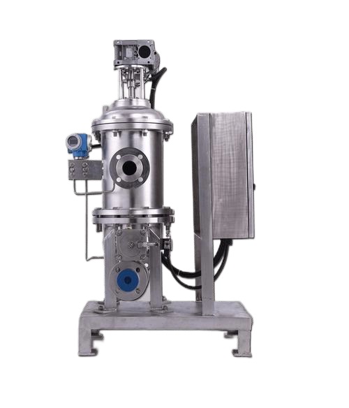
The skid as it arrived, and the number nobody owned
Two pressure vessels ran in parallel, each with a bed of anthracite over sand over garnet. Raw water came in through a common header, filtrate left through a second header, and a blower and pump handled the backwash cycle. The control philosophy was purely time-based, with a wash every fixed number of hours regardless of how much solids the bed had actually collected. Operators judged condition by looking at the inlet gauge, the outlet gauge and, on a bad day, the colour of the backwash water.
That arrangement leaves the most useful variable unmeasured. A clean bed has a small, stable pressure drop. As solids accumulate, the drop climbs. What the plant needed was not two absolute values but the gap between them, and the gap was small compared with the line pressure both taps saw all day. Our own pressure transmitters catalogue covers the single-port instruments that were already on the skid, and they are the correct choice for header pressure. They are the wrong choice for the difference.
The first conversation was therefore not about accuracy classes. It was about which physical quantity the control loop was supposed to act on. Once that was written as a differential measurement, everything downstream changed, starting with the error budget.
Why two gauge transmitters lost the argument
Subtraction looks free until the error terms are written out. Each transmitter carries an accuracy band expressed as a share of its calibrated span. With a 0 to 1 MPa span and a stated ±0.5% of span, each instrument contributes ±5 kPa of uncertainty. Two independent instruments combined in quadrature give roughly ±7 kPa, and that is before thermal drift, zero shift and the different installation temperatures of two separate bodies. On a real differential of 20 to 30 kPa, the derived value can be uncertain by a quarter or more of the quantity being controlled.
| Arrangement | Span per instrument | Typical band | Combined uncertainty on a 25 kPa signal |
| Two gauge cells subtracted in PLC | 0 to 1 MPa | ±0.5% of span each | about ±7 kPa, near 28% of reading |
| Two gauge cells, tighter spans | 0 to 250 kPa | ±0.5% of span each | about ±1.8 kPa, near 7% of reading |
| One dedicated DP cell | 0 to 100 kPa | ±0.5% of span | about ±0.5 kPa, near 2% of reading |
The middle row is the compromise some contractors reach for, and it fails for a different reason. Narrowing both spans to 250 kPa means neither instrument survives a line upset at 400 kPa without an overload rating that the original BOM never specified. A dedicated DP transmitter resolves a small difference on top of a large common-mode pressure by design, because both ports see the static pressure and the sensing cell responds only to the gap. IEC 61298-2 and IEC 60770-1 set out how those performance claims are evaluated, and reading the methods makes the distinction between span-based and reading-based error impossible to ignore. A single DP transmitter sized to the differential removes both the subtraction and the argument about which of two instruments drifted.
We did not remove the two header instruments. They still report line pressure, protect the pump and give operators a familiar number. We added a dedicated differential pressure transmitter and let the PLC stop doing arithmetic it was never qualified to do.
Freezing the line list before steel was cut
The order that went back to the skid builder was longer than the one that came in, and every added line answered a failure we had seen before. Freezing it before fabrication mattered, because a tapping point or a manifold that is not in the piping drawing becomes a cutting and welding job on site.
| Line item | Value on this skid class | Reason it is on the order |
| Measurement | Differential, high port upstream | The controlled quantity is the drop across the bed |
| Differential span | 0 to 100 kPa | Clean-bed drop sits low, fouled bed stays inside span |
| Static line pressure | 400 kPa normal, higher at pump start | Separate from the differential span |
| One-sided overload | Specified for full line pressure | A closed equalising valve puts static on one port |
| Wetted parts | 316L, with seal option for solids-bearing water | Raw side carries grit and occasional coagulant |
| Process connection | Threaded taps with isolating valves | Matches the skid’s existing fittings |
| Output | 4 to 20 mA with HART | Existing analogue input, diagnostics for the maintenance team |
| Ingress and ambient | Outdoor skid, washdown nearby | Cable entry and vent both face the weather |
| Documentation | Calibration certificate, material traceability | Required at handover and audit |
The pressure transmitters process solutions documentation we issued with the quote follows the same order, because a line list that starts with the model number tends to end with a missing static rating. A DP transmitter ordered from a catalogue line alone will arrive with the wrong static rating more often than with the wrong span. Our note on inline level measurement in modern water treatment plants covers the same discipline on the tank side of a reuse package.
Static pressure is a separate line on the order
The most expensive misunderstanding on this job was not the span. It was the assumption that a 100 kPa differential cell could simply be bolted onto a 400 kPa line. A differential device has a calibrated span and a static pressure rating, and they are independent. Static pressure effect describes how far the indicated differential moves when both ports are raised from atmosphere to operating pressure. At a low differential span that shift can be a noticeable part of the reading, so the unit has to be specified and zeroed for the pressure it will actually live at.
One-sided overpressure is the other half. A three-valve or five-valve manifold lets a technician isolate, equalise and check zero without shutting the skid down, and it also lets someone get the sequence wrong. If the equalising valve is closed when the pump starts, full line pressure arrives at one port alone. We sized the overload rating for that mistake rather than for the tidy version of the procedure, and wrote the equalising sequence into the method statement. For a differential pressure transmitter the static rating is a purchase decision, not a footnote. The LONN-3051 coplanar platform was chosen partly because its manifold interface makes that plumbing shorter and easier to inspect.
Water chemistry, wetted parts and why the raw side needed a seal
The filtrate side is nearly clean water. The raw side is not. A reuse package can receive grit, coagulant residue, iron floc and whatever the upstream process sent down that morning, and those solids collect at exactly the small tapping point the measurement depends on. 316L wetted parts were adequate on the polished side, but we specified a flush diaphragm seal with a filled capillary on the upstream tap so the sensing cell never saw the grit at all. EN 10204 3.1 material certificates were requested because the owner’s QA file requires traceability, and the elastomer choice was checked against the cleaning regime instead of left to the default BOM.
Temperature and chemistry interact here in ways a room-temperature compatibility table does not predict. Chloride-bearing water during a warm wash will stress a standard stainless diaphragm, and a sanitiser dose that looks harmless on a dosing sketch can shorten elastomer life over a season. The differential pressure transmitter on this skid was therefore ordered as an assembly, with the seal, fill fluid and capillary length named on the same line as the cell, because a seal added later by a different supplier changes the zero behaviour and the response time of the whole loop. Our note on protein solution viscosity control in ultrafiltration deals with a different membrane process but the same lesson, which is that the medium decides the front end before the electronics decide the accuracy.
A DP transmitter fitted with a matched pair of seals behaves differently again. Both capillaries need the same fill fluid, length and routing, and both need comparable sun exposure, or the assembly develops a temperature-dependent zero that no amount of re-ranging will remove. We have seen that fault read as a fouling trend more than once. On an outdoor skid the practical answer is to route both legs together, shade them where the design allows, and record the zero at a stable temperature in the commissioning file.
The first week: impulse lines, air and a zero that would not sit still
Commissioning is where a correct specification meets a physical installation. The high and low taps were a metre apart and at slightly different elevations, so with both legs full of still water the cell should have read a small fixed head, not zero. We recorded it, then trimmed it out with both ports at the same pressure and the bed settled, and logged the as-found and as-left values. That single recorded offset explained several of the odd readings the contractor had seen during factory testing.
Air was the second problem. A gas pocket trapped in one impulse leg makes the response sluggish and hysteretic, and the symptom looks like a filter that loads slowly and then jumps. Short, equal, continuously sloped legs with a way to vent at the high point fixed it. On an outdoor package the legs also need protection from standing water and from the sun heating one side more than the other, because a temperature difference between two filled legs produces a slow drift that mimics fouling. Our 4-20 mA pressure transmitter documentation spells out the loop scaling we used, and the industrial pressure transmitter pages show the enclosure and vent options available when a skid sits in the open.

Failure one: a reading that froze while the filter kept loading
Six weeks in, the trend went flat. The filter was still collecting solids, the pump current was climbing, and the reported differential had stopped moving at a plausible value. A frozen DP trace is almost never an electronics fault. It is a pressure that has been trapped on one side of the cell.
| Symptom seen on the skid | What we checked | Root cause |
| Flat DP while pump load rose | Isolated and flushed the high-side leg | Solids at the upstream tapping point |
| Zero shifted after a hot afternoon | Compared leg routing and fill | Unequal thermal exposure of the two legs |
| Noisy, jumpy signal at high flow | Vented both legs, reviewed damping | Turbulence at the tap and air in the line |
| Output pinned at 20 mA | Compared URV with the observed fouled drop | Span too narrow for a heavily loaded bed |
The permanent fix on the raw-water side was a diaphragm seal with a filled capillary, which keeps grit out of the impulse path entirely. That choice brings its own commitments, since two seals on a differential installation need matched fill fluid, capillary length and routing, or the assembly develops a temperature-dependent zero of its own. The pressure sensor vs transducer vs transmitter explainer is useful here, because a plant that calls all three devices by one name tends to order the wrong spare. Our note on solutions for high turbidity in wastewater from WFGD systems describes the same plugging mechanism on a much dirtier stream.
Failure two: negative differential after every backwash
The second fault was subtler. After each wash the reading dipped below zero for a while, then recovered. Nothing was wrong with the cell. The backwash had left the two legs in different states, with one side holding a different liquid column than the other, so the elevation term that had been trimmed out at commissioning briefly came back. Re-zeroing with both taps at the same pressure and no flow resolved it, and the procedure was added to the post-wash checklist rather than treated as a one-off adjustment.
This is the class of problem that a specification cannot prevent and a commissioning record can. It is also why we insist on as-found and as-left values at handover. A zero trimmed during a cold start, or immediately after a wash, becomes a hidden bias in every trend that follows. The absolute pressure transmitter page covers a different reference entirely, and it is worth reading before someone suggests swapping a spare across the skid, because an absolute cell open to air reads about one atmosphere rather than zero.
Turning a clean-bed baseline into a backwash trigger
With a trustworthy signal, the timer could finally be replaced by a condition. A differential pressure transmitter only earns its place on a control loop once the signal is trusted enough to drive a sequence. We logged several complete cycles, including the reading immediately after a wash and the reading at the end of a normal run, then set the trigger above the observed clean-bed baseline and below the drop at which the bed was genuinely spent. A rate-of-rise alarm was added alongside the absolute threshold, because a steadily climbing trend tells the operator that fouling is accelerating, while a single high reading may only mean a flow excursion.
The scaling had to be written once and used everywhere. LRV and URV in the transmitter, the 4 mA and 20 mA engineering values in the PLC, and the units on the HMI all had to agree. NAMUR NE 43 defines the out-of-range signal levels that distinguish a valid overrange from a sensor fault, but those conventions only help if the receiving card is configured to interpret them. We have traced more than one apparent instrument failure to a HART re-range that changed the end points while the PLC scaling stayed at the old values, so the as-left configuration became part of the handover file on this job rather than an attachment nobody opened.
Our piece on slight positive pressure control for nitrogen blanketing looks at the low end of the same problem, where a few pascals decide whether a vessel breathes in moist air. Both cases ask the same question of the loop, which is whether the number on the screen is the quantity the operator thinks it is.
What the first year of trend data actually changed
A condition-based wash changed three things on this class of package, and none of them required a new instrument after the first month. Wash frequency followed solids load instead of the clock, so water and blower energy went to the beds that needed it. Operators gained a week or more of warning before a bed reached its limit, which moved filter attention from a reactive callout to a planned task. And the trend gave the maintenance team a way to argue about upstream process changes with evidence, because a sudden shift in the fouling rate usually starts somewhere other than the filter.
We will not put a percentage saving or a payback period on this page. Those numbers depend on the raw-water quality, the tariff, the wash water cost and how the plant schedules labour, and a figure quoted without them would be a marketing claim dressed as an engineering result. What we can say is that the plant stopped using a timer as a proxy for filter condition, and that the differential reading became the variable the operators trusted. Sites considering the same change should baseline their own clean-bed drop and their own wash cost over several cycles before calculating a return. Our notes on automated polyelectrolyte preparation and dosing in water treatment process lines and how to measure density of sludge in a water treatment plant sit upstream of the same decision, because coagulant dosing and sludge load both move the fouling curve.
The handover file the plant kept
The documentation that survived the project was not the brochure. It was a folder containing the frozen line list, the manifold and impulse-line drawing, the as-found and as-left calibration values, the certificate with traceability to ISO/IEC 17025, the material certificates requested for the wetted parts, the LRV and URV scaling record, and the post-wash re-zero procedure. When a shift engineer asks why the reading sits where it does, that folder answers the question without a phone call.
Traceability tells an auditor how the numbers were produced. It does not tell them whether the loop was ranged in kPa differential or in bar, and it does not record that the upstream tap was moved after the plugging incident. Those details live in the as-built drawing and the configuration record, and the three documents have to agree. A pressure transmitter price enquiry that omits documentation is not comparable with one that includes it, because the cheaper offer often omits the manifold, the seal or the calibration file.
Where this case sits next to the general filtration guide
We also publish a general guide to differential pressure measurement for filtration and level, and the two pages are not alternatives. The guide explains the principle, span sizing, wet and dry legs, seal systems and the installation errors that apply to every such loop. This case follows one package through a year and records the decisions, failures and corrections in the order they happened. A reader choosing an instrument wants the guide. A reader deciding whether a supplier has actually commissioned a skid wants this account.
Keeping the two apart is deliberate. Both pages link to the same differential pressure transmitter product range, but they answer different questions and they do not repeat each other’s sections. A plant engineer who lands here first and needs the underlying method should go to the guide; a buyer who lands on the guide and wants evidence of field practice should come here. Our pressure measuring transducers range covers the OEM variants where a skid builder fixes the reference at build time, which is a third conversation again.
What we would specify differently on the next skid
Three changes would go into the next line list before the first tap is drawn. The DP transmitter would be ordered as a complete assembly from the first revision, with its seals and capillaries named on the same line. Flush-diaphragm seals would be specified on the raw-water side from the outset rather than added after the plugging incident. The tapping points would be placed where turbulence is lowest, with the elevation difference between them documented as a drawing dimension instead of discovered at commissioning. And the backwash trigger would be designed as a trend plus a threshold from day one, with the clean-bed baseline captured during factory testing rather than reconstructed from the first month of operation.
None of those is exotic. All three are cheaper to write into a drawing than to retrofit. Our note on chlorine flow measurement in water treatment plants makes the same point from the dosing side, and the wastewater flow measurement overview is a useful companion when the package also has to account for what leaves the filter.
What LONNMETER builds and what we will not claim
LONNMETER GROUP develops, manufactures and sells these instruments as one organisation, so the person who sizes the span is close to the bench that builds the cell and to the engineer who answers the commissioning call. The LONN-3051 coplanar platform serves differential duties where a compact manifold interface matters, the in-line mounting platform covers direct-mount single-port duties, and the LONN-2088 gauge and absolute transmitter gives sites a common spare across two reference types. Calibration is traced through deadweight testers and pressure comparators with laboratory accreditation to ISO/IEC 17025, and each shipment carries its own certificate.
We will not quote an accuracy figure, a static rating, an ingress claim or a protection marking for a configuration we have not built, and we will not present an anonymised project as a measured reference installation with named results. The china pressure transmitter page covers volume and OEM supply, and the contact page is where a skid builder sends the line list. Send the differential span, the static pressure, the medium, the tapping arrangement and the loop function with the first message, and the conversation starts from the physical quantity instead of a part number.
About us
SHENZHEN LONNMETER GROUP is a global intelligent instrument industry technology company. The group is headquartered in Shenzhen, China’s science and technology innovation center. After more than ten years of steady development, it has formed a collection of research and development, production, sales and service. A group company of measurement, intelligent control, environmental monitoring and other series of project products.
Media Contact
Company Name: LONNMETER GROUP
Contact Person: Media Relations
Email: Send Email
Country: China
Website: https://www.lonnmeter.com/
Press Release Distributed by ABNewswire.com
To view the original version on ABNewswire visit: DP Transmitter Water Filtration: A Skid Case Study in Backwash Control


